CN
CN
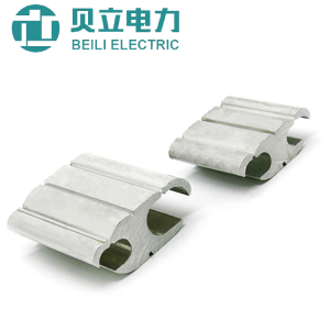
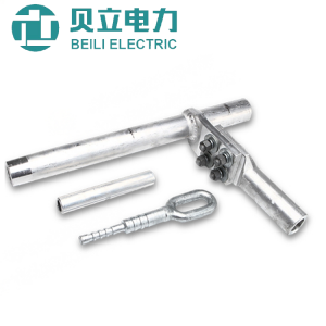
JJE Series C Type Transformer Clamp
Description:
The C-clamp for transformer is made of special aluminum alloy, which has strong conductive properties, and is suitable for both copper conductors and copper-aluminum transition conductors. This clamp is mainly used to connect and disconnect the studs and wires from transformers, switches and other equipment.
One end is not completely closed with the internally threaded post connected, and the other end is connected with the wire. The hinged block connects the internally threaded round pipe with the wire. The partially closed threaded round pipe has elasticity and can store and release the wire and stud. Energy caused by thermal expansion and contraction
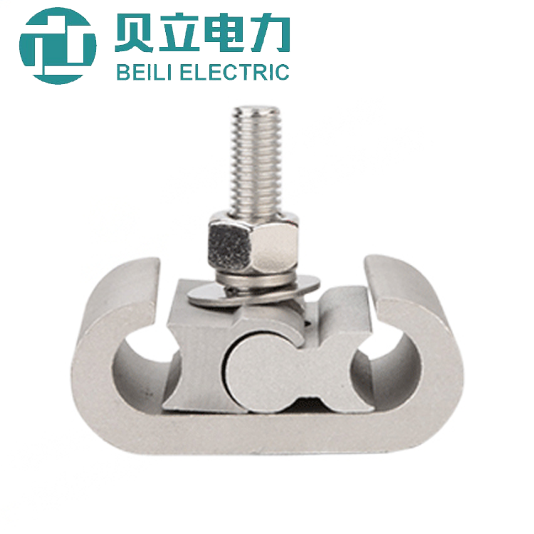
When the load increases, the thermal barrier of the wire expands, and the threaded tube will be slightly flattened. When the wire is contracted, the threaded tube is retracted due to its elasticity, and the constant contact pressure is maintained (co-breathing effect).
The hinge block installed between the threaded tube and the wire can produce a very high side pressure under a certain action, so that the C-type clamp and the wire, and a sufficient contact pressure with the transformer and the stud, so that the transformer screw The column completely matches the internally threaded tube, which greatly increases the contact surface between the transformer stud and the C-clamp, and maintains stable contact performance.
Applicable voltage level: 380v, 10kV, 110kV, 220kV, 330kV, can be used to connect aluminum head to aluminum wire, aluminum head to copper wire, aluminum head to aluminum wire
Features:
1. Breathe with wires and leads,eliminate the thermal discharge failure of the wire and equipment connection
2. Effectively reduce contact loss
3. Greatly reduce the huge loss of equipment and power outage caused by thermal failure
4. Installation is very convenient, fast and greatly reduces human factors
5. Maintenance-free and maintenance-free to improve the investment efficiency of funds
6. No special tools are needed, which can improve the investment benefit of funds
7. Greatly increases the contact surface between the equipment and the wires, improving the service life
8. Long-term reliable and safe operation of bit lines and equipment provides strong guarantee
|
Model |
Applicable Stud |
Applicable Conductor |
Wire Diameter |
Model |
Applicable Stud |
Applicable Conductor |
Wire Diameter |
|
SP-B50 |
M12 |
LJ(TJ)25 |
6.36 |
SP-B94 |
M20 |
LJ(TJ)150 |
15.75 |
|
SP-B51 |
M12 |
JKLYJ35 |
7 |
LGJ120 |
17.74 |
||
|
LJ(TJ)35 |
7.5 |
SP-B95 |
M20 |
LJ(TJ)120 |
14.25 |
||
|
LGJ35 |
8.16 |
LGJ95 |
13.6 |
||||
|
SP-B52 |
M12 |
JKLYJ50 |
8.3 |
SP-B71 |
M16 |
LJ(TJ)35 |
7.5 |
|
LJ(TJ)50 |
9 |
LGJ35 |
8.16 |
||||
|
LGJ50 |
9.6 |
LJ(TJ)50 |
9 |
||||
|
SP-B53 |
M12 |
JKLYJ70 |
10 |
SP-B72 |
M16 |
LGJ70 |
11.4 |
|
LJ(TJ)70 |
10.8 |
LJ(TJ)70 |
10.8 |
||||
|
LGJ70 |
11.4 |
JKLYJ70 |
10 |
||||
|
SP-B54 |
M12 |
LJ(TJ)95 |
12.12 |
LGJ50 |
9.6 |
||
|
LJ(TJ)120 |
14.25 |
SP-B73 |
M16 |
LJ(TJ)95 |
12.12 |
||
|
SP-B55 |
M12 |
LJ(TJ)150 |
15.75 |
LGJ95 |
13.6 |
||
|
JKLYJ185 |
16.2 |
LJ(TJ)120 |
14.25 |
||||
|
LJ(TJ)185 |
17.5 |
SP-B74 |
M16 |
LJ(TJ)150 |
15.75 |
||
|
SP-B56 |
M12 |
LJ(TJ)240 |
20 |
LGJ120 |
15.74 |
||
|
SP-B61 |
M14 |
LJ(TJ)35 |
7.5 |
SP-B75 |
M16 |
LJ(TJ)185 |
17.5 |
|
LGJ35 |
8.16 |
LJ(TJ)150 |
17.1 |
||||
|
LJ(TJ)50 |
9 |
JKLYJ185 |
16.2 |
||||
|
SP-B62 |
M14 |
LGJ70 |
11.4 |
SP-B76 |
M16 |
LGJ185 |
18.9 |
|
LJ(TJ)70 |
10.8 |
JKLYJ240 |
18.4 |
||||
|
JKLYJ70 |
10 |
SP-B77 |
M16 |
LJ(TJ)240 |
20 |
||
|
SP-B63 |
M14 |
LGJ50 |
9.6 |
SP-B81 |
M18 |
LJ(TJ)35 |
7.5 |
|
LJ(TJ)95 |
12.12 |
LGJ35 |
8.16 |
||||
|
LGJ95 |
13.6 |
LJ(TJ)50 |
9 |
||||
|
LJ(TJ)120 |
14.25 |
SP-B82 |
M18 |
LGJ70 |
11.4 |
||
|
SP-B64 |
M14 |
LGJ120 |
15.74 |
LJ(TJ)70 |
10.8 |
||
|
LJ(TJ)150 |
15.75 |
JKLYJ70 |
10 |
||||
|
SP-B65 |
M14 |
LGJ150 |
17.1 |
SP-B83 |
M18 |
LJ(TJ)120 |
14.25 |
|
LJ(TJ)185 |
17.5 |
LGJ95 |
13.6 |
||||
|
SP-B66 |
M14 |
LGJ185 |
18.9 |
LJ(TJ)95 |
12.12 |
||
|
JKLYJ240 |
18.4 |
SP-B84 |
M18 |
LJ(TJ)150 |
17.75 |
||
|
SP-B67 |
M14 |
LJ(TJ)240 |
20 |
LGJ120 |
17.74 |
||
|
SP-B91 |
M20 |
LJ(TJ)240 |
20 |
SP-B85 |
M18 |
LJ(TJ)185 |
17.5 |
|
SP-B92 |
M20 |
LGJ185 |
18.9 |
LGJ150 |
17.1 |
||
|
JKLYJ240 |
18.4 |
JKLYJ185 |
16.2 |
||||
|
SP-B93 |
M20 |
LJ(TJ)185 |
17.5 |
SP-B86 |
M18 |
LGJ185 |
18.9 |
|
LGJ150 |
17.1 |
JKLYJ240 |
18.4 |
||||
|
JKLYJ185 |
16.2 |
SP-B87 |
M18 |
LJ(TJ)240 |
20 |
Installation:
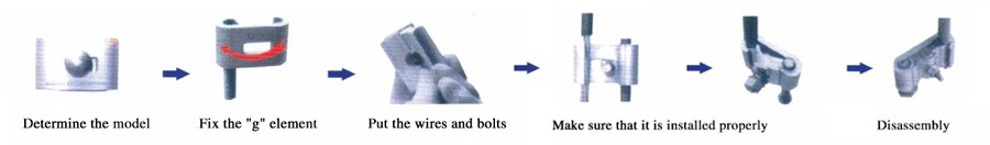
1. Determine the model: Carefully check whether the wire is consistent with the model marked on the clamp, such as: Model ZJC-B51, M12 means that the transformer’s lead screw is M12, and JKLJ35 is the outgoing wire
2.Fix the “g” -shaped element: screw it clockwise to the transformer screw, and the “g” -shaped element can be screwed and extended outward. Provisions: The female block is matched with the side of the transformer arc, the male block is matched with the wire, and the hinge block is taken out to form it (the two hinge blocks are turned into a certain angle)
3. Put the wires and bolts in place: Put the wires into the “g” -shaped grooves, and put them into a bow-shaped hinge connection according to the arc surface. You can insert the bolts on the back so that the bolts are in the middle position on the top of the hinges. Tighten the bolts with a wrench.)
4. Make sure that it is installed properly: When tightening the bolt, the last few threads should have a clear sense of force. Press the hinge clamp flat and press against the “g” -shaped element. The “g” element should be slightly deformed. (After installation, pull the wire and pull out by pulling or pulling to see if the wire and the pull out are tight)
5. Disassembly: Loosen the bolts, insert a screwdriver between the pressing block and the “C” element, and pry up with force to arch the pressing block upward.